Home ›
Tools & DIY › Why a Multimeter Reads AC Volts on a DC Supply
Tools & DIY
Why a Multimeter Reads AC Volts on a DC Supply
PBy the Pickpedia Team·5 picks compared·Last verified October 2026
Affiliate disclosure: As an Amazon Associate, Pickpedia earns from qualifying purchases. Links on this page are paid links, and we may earn a commission at no extra cost to you. This never affects our picks or scores.
This page contains affiliate links. If you buy through one we may earn a
commission, at no cost to you.
Before anything else: this page is arithmetic about a measurement, not a safety assessment.
Nothing below establishes that any particular reading on any particular circuit is safe to touch,
and the whole reason the category ratings discussed later exist is that a voltage alone never tells
you that.
With that said, the reading in the question is usually not the supply. Three
different things produce alternating volts on a meter pointed at a direct voltage, and only one of
them belongs to the equipment. The other two belong to the meter, and one of them scales directly
with the length of the leads you bought.
The first mechanism: the leads are an antenna and the meter is the other half of a divider
A handheld meter's voltage input is about 10 megohms. That is a huge resistance by the standards
of a circuit and a small one by the standards of empty space, and the gap between those two facts is
where the reading comes from.
Lay a test lead down on a bench. It is a conductor, and every conductor in a building has a
capacitance to the mains wiring in the walls, the flex of the lamp beside it, and the bench's own
metalwork. That capacitance and the meter's 10 megohms are in series across the mains, so the meter
reads its own share of a divider, with nothing connected to the probe tip at all.
How big is the capacitance? For a wire at some height above a return path it is two pi times the
permittivity of free space, times the length, divided by the natural logarithm of twice the height
over the conductor radius. The constant out front is 5.5632 times ten to the minus eleven farads per
metre. At a half metre height and a 0.8 millimetre conductor radius the logarithm is 7.1309, and the
whole length term sits on top:
A set of
60 inch silicone multimeter test
leads publishes exactly the figure this needs. Sixty inches is 1.524 metres, which comes to
11.89 picofarads. A 12 inch lead of the kind that ships in the box with a meter is
0.3048 metres and comes to 2.378 picofarads. Capacitance is strictly proportional to
length, so the ratio is exactly five, the ratio of the lengths, with nothing else in
it.
Now the divider, at 120 volts and 60 hertz. The reactance of a capacitor is one over two pi times
the frequency times the capacitance, which is 223.1 megohms for the long lead and
1,115.6 megohms for the short one. The meter reads 120 volts times its own 10
megohms over the magnitude of the series impedance:
The 60 inch lead reads 5.37 volts alternating. The 12 inch lead reads
1.08. On a 230 volt 50 hertz supply the long lead reads 8.59. These
are not errors in the meter. The meter is correctly reporting a real potential difference across its
own terminals, and it appeared because you bought longer leads.
A loose lead and a 10 megohm input
are a capacitive divider with the room. Capacitance is linear in length, so a 60 inch lead reads 5.37
volts where a 12 inch one reads 1.08, with 0.537 microamps behind it. Shunt the terminals with 10
kilohms and a ghost falls by a factor of 999, while a real source does not move.
Why that reading is both real and worthless, and how to prove it in one move
Work out the current. 120 volts across 223.1 megohms is 0.537 microamps. Half a
millionth of an amp. The same leads are rated for 10 amps on a meter's current
input, which is 18.6 million times the current behind the number on the display.
That ratio is the whole character of the thing. A capacitive source has voltage and effectively no
current, so anything you connect across it wins. Put a 10 kilohm resistor across the meter's
terminals and recompute: 120 volts times 10 kilohms over 223.1 megohms is 5.38
millivolts. The reading falls by a factor of 999.
So the diagnostic is one resistor. A capacitively coupled reading divides by roughly a
thousand when you shunt the input. A real source with a low output impedance barely moves.
If the alternating volts on your supply survive a modest shunt, they are the supply's. If they
collapse, they were the room's, arriving through your own leads.
And there is a reason to prefer the longer leads anyway, which that record states well: in a
consumer unit, an engine bay or an air handler, the point you need to probe and the place you can
safely set a meter down are rarely the same place, and five feet lets you separate them so you read
the display instead of guessing at it. Full record in our
review of the 60 inch silicone test
leads. The trade is simply that the number which buys you that reach is the same number that
multiplies the pickup by five.
The second mechanism: ripple is real, and your meter only sees part of it
Sometimes the alternating volts genuinely are on the output. A supply that rectifies mains and
smooths it with a reservoir capacitor leaves a residue, because the capacitor discharges between
charging peaks. Drawing a current I from a capacitance C at a ripple frequency f leaves a peak to
peak residue of I over f times C, and a sawtooth's root mean square value is its peak to peak figure
over two root three.
One amp from a 2,200 microfarad reservoir at a 120 hertz ripple frequency is 3.79 volts
peak to peak, which is 1.09 volts on an alternating volts range. The same
amp from 10,000 microfarads is 0.833 peak to peak and 0.241 volts. Those are
substantial readings and they are entirely honest.
Here is the part that inverts everyone's intuition. A handheld meter's alternating volts path is
specified over roughly 40 hertz to 1 kilohertz. It is a band limited instrument,
deliberately, because mains frequencies are what it is for.
A modern switching charger does not ripple at 120 hertz. It ripples at its switching frequency,
which for a compact USB-C adapter is commonly somewhere near 100 kilohertz, a hundred times
above the top of the meter's specified band. So the meter's reading on a switching supply is
not a measurement of its ripple at all. A switching supply with far more ripple energy can
read far less than a linear one with less, and the reading on it tells you about the
40 hertz to 1 kilohertz slice and nothing else.
Which means the sentence worth keeping is this: the meter does not measure how much alternating
voltage is sitting on your direct voltage. It measures how much is sitting on it between 40
hertz and 1 kilohertz.
The supplies in this catalogue, and the figures they do not publish
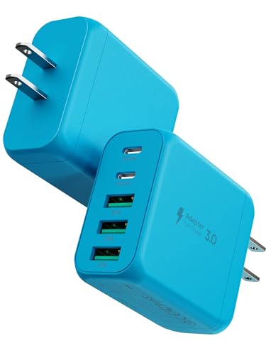
The objects in the question are exactly the sort of thing we sell. A
50 watt five port USB-C charger
block, sold as a two pack publishes five ports, two USB-C and three USB-A, a 20 watt single
USB-C fast charge port, IEC 62368-1 and FCC certification, multiple protections and a fireproof
housing. A
140 watt smart auto-stop USB-C
charger publishes up to 140 watts and a full charge detection that physically cuts the
connection when charging completes.
Neither publishes a switching frequency, an output capacitance, or a ripple figure.
Nor does any other supply in this catalogue, and there is no linear bench supply here at all. So the
second mechanism above cannot be evaluated against our own products, which is why the 2,200
microfarad and one amp in the arithmetic are representative numbers rather than published ones. The
one genuinely useful number in this area comes from the five port block's own drawbacks field, and it
is about division rather than ripple: "50W is a shared total, not per port." That is
the honest version of a specification and we have a page on exactly that habit,
USB-C charger
wattage explained.
A voltage rating and a test voltage are different numbers, and so is a category
While we are separating numbers that look alike, two more are worth doing, because both appear on
things in this catalogue and neither means what the larger figure suggests.
A
1000 volt insulated electrician
screwdriver set, eleven pieces publishes VDE and GS certification, S2 steel shafts, magnetic
black tips, flame resistance, a thin Slimfix insulation layer, a tether hole, sizes from Pozidriv PZ1
and PZ2 through Phillips PH1 and PH2, slotted 3.5 to 6.5 millimetres and Torx T15, T20 and T25 in a
foam tray, and two voltages: tested to 10,000 volts and rated to 1,000.
That is a factor of ten, and it is not a safety margin you get to spend. It is a
proof test: the insulation is subjected to ten times the working figure briefly, as
evidence that it will hold the working figure indefinitely. The number you use is the smaller one.
Our page on
whether insulated screwdrivers prevent
electric shock covers which hazard that insulation addresses and which it leaves bare, and
how to choose an
insulated screwdriver set has the selection side. More in our
review of the FESA
insulated set.
And the test leads above carry the pair that explains itself best. They publish CAT III
1000V and CAT IV 600V, and their own record says why those differ: "The rating is about the
energy available at the point of measurement, not just the voltage, which is why the two categories
carry different voltage figures." That is exactly right, and it is the ideal foil for everything above.
The entire category system exists because available energy, not voltage, is what decides what
a measurement can do to you. And the reading in this question has 0.537 microamps behind it.
A number can be a real voltage, correctly measured, and carry no energy at all.
Why this is not the hum on your stereo, although it looks like it
Our page on
why your speakers hum when
everything is plugged in describes an unwanted mains frequency voltage appearing where nobody put
one, which sounds like the same thing and is a different coupling with a different cure.
That one is magnetic. A closed loop of wire in a changing magnetic field has a
voltage induced in it equal to two pi times the frequency, times the field strength, times the
area the loop encloses, and the fix is geometric: make the loop smaller.
This one is electric. There is no loop and no area term. There is a capacitance
proportional to length, and a cure that is equally simple and completely different:
present a low impedance, or use shorter leads, or keep them off the mains flex. Two mechanisms, two
different geometric terms, two different remedies. Worth knowing which you have before changing
anything.
And a practical note on holding the probes while you do any of this. An
AORAEM helping hands magnifier with
dual alligator clips publishes a cast iron base, a 63 millimetre 2.5x glass lens on a 360 degree
rotation, and two clips on four way swivels. Clipping both probes means the reading is taken with
your hands nowhere near the leads, which removes you from the capacitance calculation entirely,
because a person is a far larger coupling plate than any wire. Its own limit is scope: "built for
medium to small items only." The clip springs themselves are the subject of
why a clip that stays shut loses its grip
first, and the record is in our
review of the AORAEM
helping hands.
The honest limit, and three things not computed
What is exact. The ratio of the two lead capacitances is exactly the ratio of their
lengths, 5.00, and that does not depend on the height, the radius or the frequency, because
those sit in a term both leads share. The divider algebra, the 0.537 microamps, the 999 fold fall
under a 10 kilohm shunt, and both ripple figures are arithmetic.
What is representative rather than published, and the list matters. The 10 megohm input
impedance is near universal on handheld meters and is published by no record we carry. The
0.8 millimetre conductor radius and 0.5 metre height are estimates, and here the
mathematics is kind: they enter only inside a logarithm, so being wrong about the height by a factor
of two changes the capacitance by about 9.7 percent, while the length, which is published,
scales it one for one. The expression itself is for a wire above a conducting plane and a workbench
is not one, so treat the absolute picofarads as an order of magnitude and the ratio as exact. The
2,200 microfarad reservoir, the one amp load, the 40 hertz to 1 kilohertz band and the 100
kilohertz switching frequency are all typical values.
Three things this page deliberately does not compute. It does not compute the actual
ripple of either charger we carry, because neither publishes a switching frequency, an
output capacitance or a ripple specification, and inventing those three would be inventing the whole
answer rather than deriving it. It does not compute what a meter's own accuracy
specification contributes, the "plus so many digits" term that dominates every reading taken
well below full scale, because no meter in this catalogue publishes one and that deserves its own
page. And it does not say whether any reading is dangerous, which is a question about
available fault energy at a particular point in a particular installation, and is precisely what the
category ratings exist to answer and what arithmetic on a published lead length cannot.
Three numbers to carry. A loose lead and a 10 megohm input make a divider with the room, and
because capacitance is linear in length a 60 inch lead reads about five times what a
12 inch one reads. The current behind that reading is around half a microamp, so
shunting the terminals with 10 kilohms collapses it by a factor of a thousand while a real source
does not move. And a meter's alternating volts range is a band, roughly 40 hertz to
1 kilohertz, which is why a switching supply full of 100 kilohertz ripple can read lower than a
linear one with a tenth as much.
Why a Multimeter Reads AC Volts on a DC Supply at a glance
AORAEM Helping Hands Magnifier with Dual Alligator Clips
hobbyists soldering and inspecting small detailed parts
Heavy cast iron base keeps work steady
Built for medium to small items only
Why you can trust this guide
We compared these picks using verified manufacturer specifications, current retailer listings, and patterns in owner feedback, alongside editorial research. We focus on measurable differences such as performance, capacity, usability, and build quality. Pickpedia does not present editorial research as laboratory testing, and we do not claim hands-on testing unless it was actually performed.
Best for Panel work and vehicle diagnostics where the meter cannot sit next to the probe point
8.8/ 10 Pickpedia editorial score
A set of 60 inch multimeter test leads with soft silicone insulation and universal 4mm banana plugs, rated CAT III 1000V and CAT IV 600V at 10A, for electrical, automotive and HVAC testing.
Best for Charging several devices from one outlet at home or travel
8.8/ 10 Pickpedia editorial score
A compact 50W USB wall charger with five ports (dual USB-C and three USB-A), a 20W single USB-C fast-charge port, IEC 62368-1 and FCC certification with multiple safety protections, and a fireproof housing, sold as a two-pack for home and travel.
BrandEIZLXQ
TypeMulti-port USB wall charger
Total output50W shared
Ports5 total: 2 USB-C, 3 USB-A
Single USB-CUp to 20W
CertificationIEC 62368-1, FCC
ProtectionOverheat, overcurrent, overcharge, short circuit, auto-stop
HousingFireproof ABS and PC
Pack2 chargers
ColourBlue
Pros
Five ports, dual USB-C and three USB-A
20W USB-C port for fast phone top-ups
One outlet replaces a cluster of chargers
IEC and FCC certified with safety protections
Compact and travel-friendly
Good-value two-pack
Cons
50W is a shared total, not per port
Simultaneous charging is slower per device
Value brand, so you trust the stated certifications
Best for Safe overnight and high-power USB-C charging
8.8/ 10 Pickpedia editorial score
A compact 140W USB-C fast charger with smart full-charge detection that physically cuts the connection when charging completes, made for safe overnight use.
TypeUSB-C wall charger
Max powerUp to 140W
Smart featureFull-charge detection and physical auto disconnect
Device supportWide USB-C: phones, tablets, many laptops
Best for Electricians working on live low-voltage circuits
8.8/ 10 Pickpedia editorial score
The FESA 11-piece insulated screwdriver set suits electricians and technicians who work on live circuits. Every driver is VDE and GS certified, tested up to 10,000 volts AC and rated to 1,000 volts AC to IEC 60900. Slim S2 steel shafts with magnetic black tips reach narrow spaces. The kit covers Pozidriv, Phillips, slotted and Torx, stored in a foam tray.
Best for hobbyists soldering and inspecting small detailed parts
8.4/ 10 Pickpedia editorial score
The AORAEM Helping Hands is a soldering and hobby station with a heavy cast iron base, a 2.5x glass magnifier, and two alligator clips on 4-way swivels. The 63mm chromed lens rotates a full 360 degrees for close up inspection, while the clips and arms adjust to many angles. Its sturdy base holds circuit boards, jewelry, and small crafts steady for soldering, gluing, and detailed assembly.